Here are some pictures of the keel reinforcement project underway, in chronological order, older to newer, top to bottom (updated August 7, 2021)...
Sole boards lifted; hoses and wires still in place.

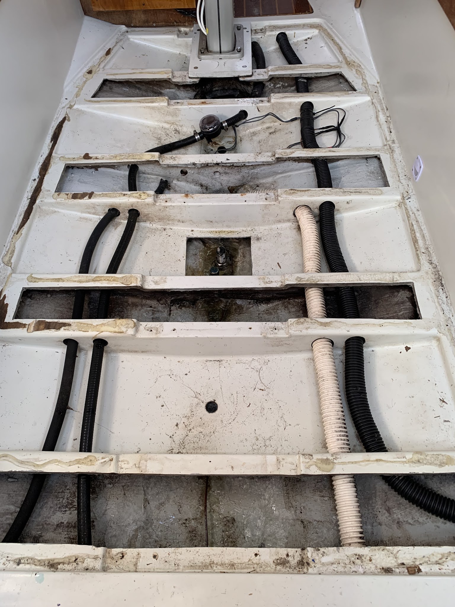
Hoses and wires cleared.

One compartment of the hull liner cut out. Lateral stringer floors that were molded into the hull liner were obviously twisted and bent from forces acting on the keel.

Looking aft, from the area of the mast. The furthest aft keel bolt is toward the top of the image.

Two forward compartments of the hull liner cut out, opening both the shallow (aft) and deep (forward) sections of the bilge.

All the fiberglass bits cut out of the liner except for the lateral ribs which I cut out intact in case I needed to reuse them. (I did not.)

All 8 keel bolts removed one at a time, and mounting surface cleaned, washers replaced, 1-inch studs re-bedded with 3M 4200, and nuts torqued to 300 ft/lbs per specifications.

9 stringer floors cut from 3/4" structural fiberglass composite Coosa board, Bluewater 26 formulation, laid out with their cardboard templates. Wore out 4 jigsaw blades making the cuts in this tough material!

Rough fitting of the 9 stringer floors. So far, so good.

All 9 stringer floors shaped carefully, laid up with fiberglass, and bonded to the hull and keel stub, including a double board fit tightly under the mast step for extra support and one board forward under the lip of the hull liner (not in view here). The forward section of the lightning wire was cleared through the access hole beneath the mast step. For the bonding, I used a methacrylate (MMA) two-part structural adhesive, a generic version of Plexus (which I could not find available in stock) named Infinity Bond, formulation 310. Let's hope so.

Stringer floors tabbed in to the hull and keel stub along their full length, and then reinforced with multiple layers of woven glass mat. I used West System epoxy resin with slow hardener (because of summer temperatures here in Michigan), and supplemented the epoxy with 404 high-density adhesive filler for strength.

Longitudinal braces cut, shaped, bonded, tabbed in, and reinforced with multiple layers of glass. All access holes for wiring, bilge pump and drain hoses, and for water evacuation were drilled and sealed with multiple coats of epoxy. The width of support boards for the bilge inspection sole board required deviating from nice alignment of the longitudinal braces, but their strength was not compromised. I prioritized function over form.

Fiberglass preparation primer and 1 1/2 coats of white Pettit epoxy BilgeCoat paint applied.

Lightning dissipation grid with 10-gauge bare copper wire connected to bow, shroud bases, engine, and keel bolt. Bracket holder for water sensor installed in a way that is removable for cleaning. Bilge pump hoses run and fittings connected. Head sink drain line and icebox drain line run.

The first compartment aft of the mast contains a WaterWitch electronic water sensor to turn on the power bilge pump when set in the Automatic setting. It is not yet wired to the panel. In the second compartment aft is routed the pickup for the power bilge pump with gross and fine strainers. This pump is mounted in the engine compartment. The third bilge compartment aft has the pickup with anti-backflow valve for the manual bilge pump mounted in the cockpit.
Maybe just a few more pictures to come...